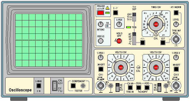
Cathode Ray Oscilloscopes better known as CRO, or there is a mention as a cathode ray oscilloscope or oscilloscope only. Benefits Osciloscope (CRO) is to measure the quantities: voltage, frequency, period, shape and phase difference signal. There are various forms of electrical signals, ie sinusoidal, triangular or triangle, square or square, pulse or pulse. Various forms of electrical signal that can be easily measured voltage, period and frequency can be determined how to use the device Osciloscope (CRO) is.
Oscilloscope (CRO) there are two types, type 1 and type 2 chanel chanel. With 2 channel CRO we can display two signals simultaneously / once in the display, ie the signal on the input path channel 1 and channel 2. Before using better CRO CRO we know the specifications that will be used. CRO general specifications that must be known, among others.
Specifications Oscilloscope (CRO)
- horizontal Axis
- vertical Axis
- Sweep Time Circuit
- trigering
- Intensity Modulation
- Power Source
the purpose of knowing the technical specifications of the oscilloscope (CRO) so we know the maximum and minimum limits of the measuring signal oscilloscope capability. In addition to knowing the specifications CRO we can avoid setting up CRO errors in measurement.
Button Functions In Panel Oscilloscope
- Button Volt / Div
This button function is to set the measurement scale in each division Oscilloscope CRT screen, this button can be set from 5 mVolt / div to 20 Volt / Div.
- Button Time / Div
Function buttons Time / Div to determine the value of the sweep time in each division Y CRT screen. This button can be set from the range of 0.5 uS / div to 0.2 S / Div.
- Position button Trace
Position button is a button that serves to adjust the position of the trace / signal measured vertically and horizontally. There are three key position on the panel 2 channel CRO, namely X-POS which serves to adjust the position of a trance to the plane of division X (vertical) and Y-POS1, Y-POS2 which serves to adjust the position of the plane of division Y trace on a CRT screen.
- Switch Coupling Input CRO
Switch coupling is a button that serves to determine the coupling is used in the measurement (AC / DC / GND) DC and AC signals. This setting is required for the measurement of AC and DC signals, especially on a DC signal measurement we have to make sure the position of this switch in the DC position in order to perform the measurement.
- Intense button and Focus
Both of these buttons (intense and focus) function to set the trace display and the measurement screen. Berfunsi intense buttons to adjust the screen brightness while the focus button to adjust the level of sharpness of the trace.

0 Response to "Cathode Ray Oscilloscope (CRO) "
Post a Comment